


FY•X is a professional China high quality 14S 48V 100A Smart BMS for Automated Guided Vehicle manufacturer and supplier, if you are looking for our products with low price, consult us now!
This FY•X high quality 14S 48V 100A Smart BMS for Automated Guided Vehicle is a BMS specially designed by Wenhong Technology Company for battery packs for electric bicycles and drones. It is suitable for 10-14 string lithium batteries with different chemical properties, such as lithium ion, lithium polymer, lithium iron phosphate, etc.The BMS can report the corresponding voltage, current, temperature, and protection status information of the battery pack in a timely manner.
It has a CAN communication interface that can be used to set various protection voltage, current, temperature and other parameters, which is very flexible. The protection board has strong load capacity and the maximum sustainable discharge current can reach 100A.
● 13 batteries are protected in series.
● Charging and discharging voltage, current, temperature and other protection functions.
● Output short circuit protection function.
● Three-way battery temperature, BMS ambient temperature, FET temperature detection and protection.
● Passive balancing function.
● Accurate SOC calculation and real-time estimation.
● Protection parameters can be adjusted through the host computer.
● CAN and RS485 communication can monitor the battery pack information through the host computer or other instruments, and choose one of the two for real-time communication.
● Multiple sleep modes and wake-up methods.
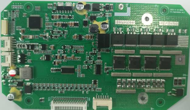
Real picture of the front of the BMS

Real picture of the back of BMS

Board front and back
|
Details |
Min. |
Typ. |
Max |
Error |
Unit |
||||||
|
Battery |
|||||||||||
|
Battery Gas |
LiCoxNiyMnzO2 |
|
|||||||||
|
Battery Links |
13S |
|
|||||||||
|
Absolute Maximum Rating |
|||||||||||
|
Input Charging Voltage |
|
54.6 |
|
±1% |
V |
||||||
|
Input Charging Current |
|
30 |
36 |
|
A |
||||||
|
Output Discharging Voltage |
45.5 |
46.8 |
54.6 |
|
V |
||||||
|
Output Discharging Current |
|
80 |
120 |
|
A |
||||||
|
Continuous Output Discharging Current |
≤100 |
A |
|||||||||
|
Ambient Condition |
|||||||||||
|
Operating Temperature |
-30 |
|
85 |
|
℃ |
||||||
|
Humidity (No Water-Drop) |
0% |
|
|
|
RH |
||||||
|
Storage |
|||||||||||
|
Temperature |
-20 |
|
65 |
|
℃ |
||||||
|
Humidity (No Water-Drop) |
0% |
|
|
|
RH |
||||||
|
Protection Parameters |
|||||||||||
|
Over-Charge Voltage Protection 1 (OVP1) |
4.200 |
4.250 |
4.300 |
±50mV |
V |
||||||
|
Over-Charge Voltage Protection Delay Time1(OVPDT1) |
1 |
2 |
5 |
|
S |
||||||
|
Over-Charge Voltage Protection 2(OVP2) |
4.250 |
4.300 |
4.350 |
±50mV |
V |
||||||
|
Over-Charge Voltage Protection Delay Time2 (OVPDT1) |
2 |
4 |
7 |
|
S |
||||||
|
Over-Charge Voltage Protection Release (OVPR) |
4.100 |
4.150 |
4.200 |
±50mV |
V |
||||||
|
Over-Discharge Voltage Protection 1 (UVP1) |
3.400 |
3.500 |
3.600 |
±100mV |
V |
||||||
|
Over-Discharge Voltage Protection Delay Time 1(UVPDT1) |
1 |
2 |
5 |
|
S |
||||||
|
Over-Discharge Voltage Protection 2 (UVP2) |
2.900 |
3.000 |
3.100 |
±100mV |
V |
||||||
|
Over-Discharge Voltage Protection Delay Time 2(UVPDT2) |
5 |
8 |
12 |
|
S |
||||||
|
Over-Discharge Voltage Protection Release (UVPR) |
3.450 |
3.550 |
3.650 |
±100mV |
V |
||||||
|
Over-Current Charge Protection 1 (OCCP1) |
33 |
36 |
40 |
|
A |
||||||
|
Over-Current Charge Protection Delay Time1 (OCPDT1) |
1 |
3 |
6 |
|
S |
||||||
|
Over-Current Charge Protection Release1 |
Delay 60±5s automatic release or discharge |
||||||||||
|
Over-Current Discharge Protection0 (OCDP0) |
130 |
150 |
170 |
±20 |
A |
||||||
|
Over-Current Protection Delay Time0 (OCPDT0) |
1 |
3 |
6 |
|
S |
||||||
|
Over-Current Discharge Protection Release 0 |
Delay 60±5s automatic release or discharge |
S |
|||||||||
|
Over-Current Discharge Protection1 (OCDP1) |
195 |
220 |
245 |
±25 |
A |
||||||
|
Over-Current Protection Delay Time1 (OCPDT1) |
40 |
80 |
200 |
|
mS |
||||||
|
Over-Current Discharge Protection Release 1 |
Delay 60±5s automatic release or discharge |
||||||||||
|
Short circuit current protection |
440 |
|
800 |
|
A |
||||||
|
Short circuit current protection delay time |
|
400 |
800 |
|
uS |
||||||
|
Short circuit protection Release |
Disconnect the load and delay 30±5s to automatically release or charge |
||||||||||
|
Short circuit instructions |
Short circuit description: The short circuit current is less than the minimum value or higher than the maximum value value may cause the short-circuit protection to fail and the short-circuit current to exceed 1000A, short circuit protection is not guaranteed, and short circuiting is not recommended. road protection test |
||||||||||
|
Discharge high temperature protection value |
70 |
75 |
80 |
|
℃ |
||||||
|
Discharge high temperature release value |
65 |
70 |
75 |
|
℃ |
||||||
|
Discharge low temperature protection value |
-25 |
-20 |
-15 |
|
℃ |
||||||
|
Discharge low temperature release value |
-20 |
-15 |
-10 |
|
℃ |
||||||
|
Charging high temperature protection value |
45 |
50 |
55 |
|
℃ |
||||||
|
Charging high temperature release value |
40 |
45 |
50 |
|
℃ |
||||||
|
Charging low temperature protection value |
-5 |
0 |
5 |
|
℃ |
||||||
|
Charging low temperature release value |
0 |
5 |
10 |
|
℃ |
||||||
|
Cell balance |
|||||||||||
|
Bleed Start Point |
4.000 |
4050 |
4100 |
|
mV |
||||||
|
Bleed Accuracy |
|
4020 |
|
|
mV |
||||||
|
Bleed Current |
40 |
|
55 |
|
mA |
||||||
|
Balance Mode |
Charge equalization |
||||||||||
|
Current Consumption |
|||||||||||
|
Normal Mode |
|
15 |
20 |
|
mA |
||||||
|
Sleep mode |
|
500 |
650 |
|
uA |
||||||
|
Ship mode |
|
30 |
100 |
|
uA |
||||||
|
Predischarge time |
150mS±20mS |
||||||||||
|
Delay closing time after MOS is turned on |
100mS±20mS |
||||||||||
Note: When the discharge current is greater than 3A, under-voltage will not be protected, and over-discharge and low-temperature discharge will not be protected.
The above parameters are recommended values and users can modify them according to actual applications.

Protection principle block diagram

Size 164*94 Unit: mm Tolerance: ±0.5mm
Protection board thickness: less than 20mm (including components)
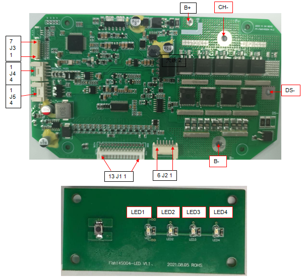
Protection board wiring diagram
|
Item |
Details |
|
|
B+ |
Connect to Positive Side of the pack. |
|
|
B- |
Connect to Negative Side of the pack. |
|
|
CH- |
Charging Negative Port. |
|
|
DS- |
Discharging Negative Port. |
|
|
J1 |
1 |
Connect to Negative of Cell 1. |
|
2 |
Connect to Positive Side of Cell 1. |
|
|
3 |
Connect to Positive Side of Cell 2. |
|
|
4 |
Connect to Positive Side of Cell 3. |
|
|
5 |
Connect to Positive Side of Cell 4. |
|
|
6 |
Connect to Positive Side of Cell 5 |
|
|
7 |
Connect to Positive Side of Cell 6 |
|
|
8 |
Connect to Positive Side of Cell 7 |
|
|
9 |
Connect to Positive Side of Cell 8 |
|
|
10 |
Connect to Positive Side of Cell 9 |
|
|
11 |
Connect to Positive Side of Cell 10 |
|
|
12 |
Connect to Positive Side of Cell 11 |
|
|
13 |
Connect to Positive Side of Cell 12 |
|
|
14 |
Connect to Positive Side of Cell 13 |
|
|
J2(NTC) |
1 |
NTC1 10K |
|
2 |
||
|
3 |
NTC2 10K |
|
|
4 |
||
|
5 |
NTC3 10K |
|
|
6 |
||
|
J3(LED) |
1 |
V_LED |
|
2 |
SW_LED |
|
|
3 |
GND |
|
|
4 |
LED4 |
|
|
5 |
LED3 |
|
|
6 |
LED2 |
|
|
7 |
LED1 |
|
|
J4 |
1 |
V5.0 positive pole |
|
2 |
H CAN communication H line |
|
|
3 |
L CAN communication L line |
|
|
4 |
V5.0 negative pole |
|
|
J5 |
1 |
V5.0 positive pole |
|
2 |
B RS485-B communication line |
|
|
3 |
A RS485-A communication line |
|
|
4 |
V5.0 negative pole |
|
Check battery level
When the battery is in standby mode, short press the power button once to display the current battery capacity.
|
Current power LED1(emerald green) LED2(emerald green) LED3(emerald green) LED4(emerald green) |
Current power LED1(emerald green) LED2(emerald green) LED3(emerald green) LED4(emerald green) |
Current power LED1(emerald green) LED2(emerald green) LED3(emerald green) LED4(emerald green) |
Current power LED1(emerald green) LED2(emerald green) LED3(emerald green) LED4(emerald green) |
Current power LED1(emerald green) LED2(emerald green) LED3(emerald green) LED4(emerald green) |
|
88%≤C≤100% |
Bright |
Bright |
Bright |
Bright |
|
75%≤C≤87% |
Bright |
Bright |
Bright |
Bright |
|
63%≤C≤74% |
Bright |
Bright |
Bright |
Bright |
|
50%≤C≤62% |
Bright |
Bright |
flash |
flash |
|
38%≤C≤49% |
Bright |
Bright |
destroy |
destroy |
|
25%≤C≤37% |
Bright |
flash |
destroy |
destroy |
|
13%≤C≤24% |
Bright |
destroy |
destroy |
destroy |
|
0%≤C≤12% |
flash |
destroy |
destroy |
destroy |
The battery displays the charging status when charging:
|
Current battery level |
LED1(red) |
LED2(green) |
LED3(grenn) |
LED4(green) |
|
0≤C≤24% |
flash |
destroy |
destroy |
destroy |
|
25%≤C≤49% |
Bright |
flash |
destroy |
destroy |
|
50%≤C≤74% |
Bright |
Bright |
flash |
destroy |
|
75%≤C≤99% |
Bright |
Bright |
Bright |
flash |
|
C=100% |
Bright |
Bright |
Bright |
Bright |
Charging abnormal protection display status:
|
conservation project |
Show rules |
LED1(red) |
LED2(green) |
LED3(green) |
LED4(green) |
|
Charging current is too large |
Flashes 2 times per second |
flash |
flash |
flash |
flash |
|
Charging temperature is too low |
Flashes 2 times per second |
destroy |
destroy |
flash |
flash |
|
Charging temperature is too high |
Flashes 3 times per second |
flash |
flash |
destroy |
destroy |
|
Large cell voltage difference |
Led1, Led3flash |
flash |
destroy |
flash |
destroy |
|
Over discharge protection |
Led2, Led4flash |
destroy |
flash |
destroy |
flash |
Power on: Short press + long press for 2 seconds, LED1~LED4 will light up in sequence, turn on the output, and the power will continue to be displayed in the power-on state (the power cannot be turned on in the over-discharge protection state). After turning on, if there is no charge or discharge (judged by the charge and discharge current, the minimum detection current is 400mA, if it is less than 400mA, it is considered that there is no current), it will automatically enter the shutdown state after 1 hour of being turned on.
Shutdown: 1. Short press + long press for 2 seconds, LED4~LED1 will go out in sequence, and the output will be turned off.
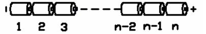
Battery connection sequence diagram
Warning: When connecting the protective plate to the battery cells or removing the protective plate from the battery pack, the following connection sequence and regulations must be followed; if operations are not performed in the required order, the components of the protective plate will be damaged, resulting in the protective plate being unable to protect the battery. core, causing serious consequences.
Preparation: As shown in Figure 13, connect the corresponding voltage detection cable to the corresponding battery core. Please pay attention to the order in which the sockets are marked.
Steps to install protective board:
Step 1: Solder the CH-\DS- line to the CH-\DS- pad of the protection board while connecting the charger and load;
Step 2: Connect the negative pole of the battery pack to B- of the protection board;
Step 3: Connect the positive terminal of the battery pack to B+ of the protection board;
Step 4: Connect the battery pack and battery strip to J1 of the protection board;
Step 5: Connect the temperature detection cable to J2 of the protection board;
Step 6: Charge and activate.
Steps to remove the protective plate:
Step 1: Disconnect all chargers\loads
Step 2: Unplug the battery pack’s battery strip connector J1;
Step 3: Remove the connecting wire connecting the positive electrode of the battery pack from the B+ pad of the protective plate
Step 4: Remove the connecting wire connecting the negative electrode of the battery pack from the B- pad of the protective plate
Additional notes: Please pay attention to electrostatic protection during production operations.
|
|
Device type |
Model |
Encapsulation |
Brand |
Dosage |
Position |
|
1 |
Chip IC |
BQ7694003DBT |
TSSOP44 |
TI |
1PCS |
U14 |
|
2 |
Chip IC |
APM32E103RCT6 |
TQFP64 |
Extreme sea |
1PCS |
U18 |
|
3 |
Patch MOS tube |
CRSS042N10N |
TO263 |
China Resources Micro |
5PCS |
MC1,2,3,4,5,6 |
|
4 |
Patch MOS tube |
SS018N08LS |
TO220SM |
Si Kai |
8PCS |
MD1,2,3,4,5,6,7,8,9,10 |
|
5 |
PCB |
Fish14S004 V1.2 |
164*94*2.0mm |
|
1PCS |
|
Note: Chip transistor: MOS tube if out of stock, our company may use other models with similar specifications to replace.
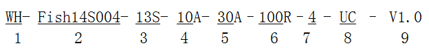
1 Wenhong company logo;
2 Protection board model -- (This protection board model is Fish14S004, other types of protection boards are marked, this character number is not limited)
3 The number of battery strings supported by the required protection board -- (this type of protection board is suitable for 14S battery packs);
4 Charging current value -- 10A means that the maximum support for continuous 10A charging;
5 Discharge current value - 30A indicates that the maximum support for continuous 30A charging;
6 Balance resistance size - directly fill in the value, such as 100R, then the balance resistance is 100 ohms;
7 Battery type - A number of digits, the specific number indicates the battery type is as follows;
|
1 |
Polymer |
|
2 |
LiMnO2 |
|
3 |
LiCoO2 |
|
4 |
LiCoxNiyMnzO2 |
|
5 |
LiFePO4 |
8 Communication mode - a letter represents a communication mode, I represents IIC communication, U represents UART communication, R represents RS485 communication, C represents CAN communication, H represents HDQ communication, S represents RS232 communication,0 represents no communication, this product UC represents UART+CAN dual communication;
9 Hardware version -- V1.0 indicates that the hardware version is 1.0.
The model of this protection board is: WH-Fish14S004-13S-30A-80A-0-4-RC-V1.2, please click this model when placing bulk orders.
1. Do not use the battery aging cabinet to measure the voltage of each battery in the battery pack when charging and discharging the battery pack equipped with the protection board
The protective panel and battery may be damaged.
2, this protection board does not have 0V charging function, once the battery appears 0V, the battery performance will be seriously degraded, and even may be damaged, in order not to
If the battery is damaged, the user needs to charge it regularly to replenish the power when it is not used for a long time (the battery pack capacity is more than 15AH, and the storage exceeds 1 month); while
In use after the discharge of power must be charged within 12 hours to prevent the battery due to self-consumption and discharge to 0V. The customer is required to have a clear case in the battery
Displays a battery identifier that users regularly maintain.
3, the protection board has no anti-charge protection function, if the charger polarity is reversed, it may damage the protection board.
4, this protection board shall not be used in medical treatment, and will affect the personal safety of the product.
5, if the user in the production, storage, transportation and use of the above reasons caused by the accident, our company will not assume any responsibility.
6, the specification is the performance confirmation standard, in the case of meeting the required performance of the specification, our company will change part of the material according to the order
The type or brand of the material, and no longer separately notified.
7. The short-circuit protection function of this management system is suitable for a variety of application scenarios, but it cannot guarantee that it can be short-circuit under any conditions. When the battery pack and short circuit
The total internal resistance value of the circuit is less than 40mΩ, the battery pack capacity exceeds 20% of the rated value, the short circuit current exceeds 1500A, and the inductance of the short circuit is very abnormal
If the total length of large or short-circuited wires is very long, please test to determine whether the management system can be used.
8. When welding battery leads, there must be no wrong connection or reverse connection. If it is indeed misconnected, the board may be damaged and needs to be retested
Then it can be used.
9, assembly management system should not directly contact the surface of the battery, so as not to damage the circuit board. The assembly should be strong and reliable.
10, in use, pay attention to the lead, soldering iron, solder, etc. do not touch the components on the circuit board, otherwise it may damage the circuit board.
Pay attention to anti-static, moisture-proof, and waterproof during use.
11, please follow the design parameters and conditions of use during use, shall not exceed the value in this specification, otherwise it may damage the management system. battery
If no voltage output is found or no power is charged after the system is combined with the management system for the first time, check whether cables are correctly connected.


