

You can rest assured to buy 7S 24V 15A Hardware BMS for E-scooter from our factory and we will offer you the best after-sale service and timely delivery.
As the professional manufacture, we would like to provide you 7S 24V 15A Hardware BMS for E-scooter. And we will offer you the best after-sale service and timely delivery.
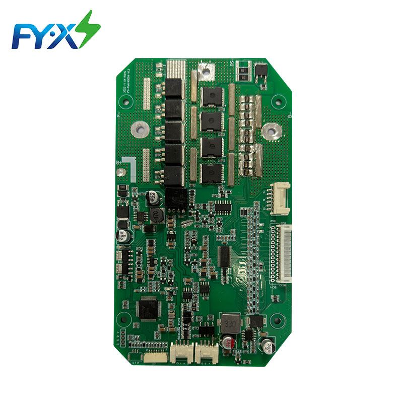
This product is a BMS specially designed by Huizhou Feiyu New Energy Technology Co., Ltd. for scooter battery packs. It is suitable for 7-string lithium batteries with different chemical properties, such as lithium ion, lithium polymer, lithium iron phosphate, etc.
It has charging and discharging over-voltage, over-current, short circuit and high and low temperature protection, which is safe and reliable. The protection boardhas strong load capacity and the maximum sustainable discharge current can reach 15A.
● Seven batteries are protected in series.
● Charging and discharging voltage, current, temperature and other protection functions.
● Output short circuit protection function.
● Charge and discharge high and low temperature protection function.
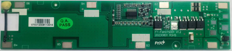
Figure 1: BMS front view, for reference only
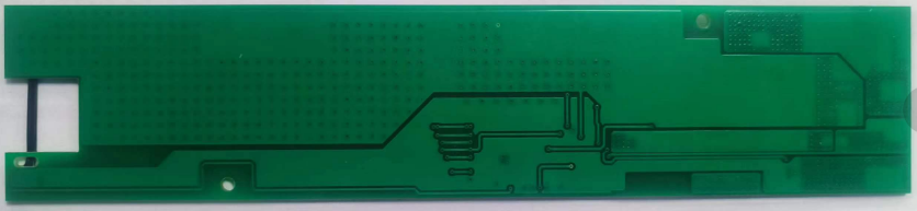
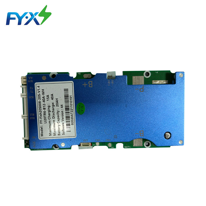
Figure 2: BMS back side picture, for reference only
|
Specification |
Min. |
Typ. |
Max |
Error |
Unit |
|||||
|
Battery |
||||||||||
|
Battery Type |
LiCoxNiyMnzO2 |
|
||||||||
|
Number of battery strings |
7S |
|
||||||||
|
Absolute Maximum Ratings |
||||||||||
|
Charging Voltage Input |
|
29.4 |
|
±1% |
V |
|||||
|
Recharging Current |
|
3 |
5 |
|
A |
|||||
|
Discharge Output Voltage |
19.6 |
25.9 |
29.4 |
|
V |
|||||
|
Discharge output current |
|
|
15 |
|
A |
|||||
|
Sustainable working current |
≤15 |
A |
||||||||
|
environmental conditions |
||||||||||
|
Operating temperature |
-30 |
|
75 |
|
℃ |
|||||
|
humidity |
0% |
|
|
|
RH |
|||||
|
Storage |
||||||||||
|
Storage temperature |
-20 |
|
60 |
|
℃ |
|||||
|
Storage humidity |
0% |
|
|
|
RH |
|||||
|
Protection parameters |
||||||||||
|
Overcharge protection value |
|
4.2 |
|
±50mV |
V |
|||||
|
Overcharge protection delay |
500 |
1000 |
2000 |
|
mS |
|||||
|
Overcharge release value |
|
4.1 |
|
±50mV |
V |
|||||
|
Over discharge protection value |
|
2.8 |
|
±100mV |
V |
|||||
|
Over-discharge protection delay |
500 |
1000 |
2000 |
|
mS |
|||||
|
Over-discharge protection release value |
|
3.0 |
|
±100mV |
V |
|||||
|
Charging circuit FUSE |
5A |
|||||||||
|
|
FUSE fuse is unrecoverable |
|||||||||
|
|
|
|||||||||
|
Discharge overcurrent 1 protection value |
28 |
33 |
38 |
|
A |
|||||
|
Discharge overcurrent 1 protection delay |
500 |
1000 |
2000 |
|
mS |
|||||
|
Discharge overcurrent 1 release conditions |
disconnect load release |
|||||||||
|
Discharge overcurrent 2 protection value |
57 |
67 |
77 |
|
A |
|||||
|
Discharge overcurrent 2 protection delay |
30 |
100 |
200 |
|
mS |
|||||
|
Discharge overcurrent 2 release conditions |
disconnect load release |
|||||||||
|
Discharge short circuit protection value |
147 |
167 |
187 |
|
A |
|||||
|
Discharge short circuit protection delay |
|
300 |
800 |
|
uS |
|||||
|
Discharge short circuit protection release conditions |
disconnect load release |
|||||||||
|
Discharge circuit FUSE |
30A |
|||||||||
|
|
FUSE fuse is unrecoverable |
|||||||||
|
Discharge high temperature protection value |
65 |
70 |
75 |
|
℃ |
|||||
|
Discharge high temperature release value |
60 |
65 |
65 |
|
℃ |
|||||
|
Charging high temperature protection value |
45 |
50 |
55 |
|
℃ |
|||||
|
Charging high temperature release value |
40 |
45 |
50 |
|
℃ |
|||||
|
Charging low temperature protection value |
-5 |
0 |
5 |
|
℃ |
|||||
|
Charging low temperature release value |
0 |
5 |
10 |
|
℃ |
|||||
|
Discharge low temperature protection value |
-25 |
-20 |
-15 |
|
℃ |
|||||
|
Discharge low temperature release value |
-20 |
-15 |
-10 |
|
℃ |
|||||
|
Power consumption parameters |
||||||||||
|
Normal power consumption |
|
57 |
100 |
|
uA |
|||||
|
Power consumption after undervoltage |
|
17 |
50 |
|
uA |
|||||

Figure 12: Dimensions 189*40 Unit: mm Tolerance: ±0.5mm
Protection board thickness: less than 10mm (including components)
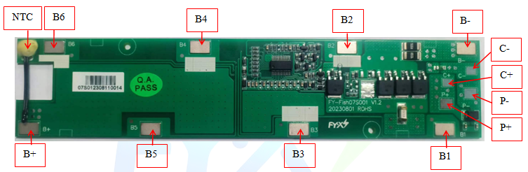
11: Protection board wiring diagram
|
Item |
Details |
|
|
P+ |
Discharging Positive Port. |
|
|
C+ |
Charging Positive Port. |
|
|
P- |
Discharging Negative Port. |
|
|
C- |
Charging Negative Port. |
|
|
|
1 |
B-Connect to Negative Side of Cell1 |
|
2 |
B1Connect to Positive Side of Cell 1 |
|
|
3 |
B2Connect to Positive Side of Cell 2 |
|
|
4 |
B3Connect to Positive Side of Cell 3 |
|
|
5 |
B4Connect to Positive Side of Cell 4 |
|
|
6 |
B5Connect to Positive Side of Cell 5 |
|
|
7 |
B6Connect to Positive Side of Cell 6 |
|
|
8 |
B+Connect to Positive Side of Cell 7 |
|
|
NTC |
|
Temperature Sensor |
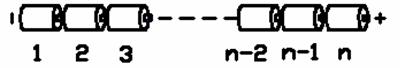
Figure 12:Battery connection sequence diagram
Warning: When connecting the protective plate to the battery cells or removing the protective plate from the battery pack, the following connection sequence and regulations must be followed; if operations are not performed in the required order, the components of the protective plate will be damaged, resulting in the protective plate being unable to protect the battery. core, causing serious consequences.
Preparation work: As shown in Figure 12, weld the corresponding nickel strip of the battery core to the corresponding pad of the protective plate. Please note the order indicated.
Steps to install protective board:
Step 1: Solder the P+/C+/P-/C- lines to the P+/C+/P-/C- pads of the protection board without connecting the charger and load;
Step 2: Connect the negative pole of the battery pack to B- of the protection board;
Step 3: Weld B1, B2, B3, B4, B5, B6, B+ to the corresponding pads of the protection board in sequence;
Steps to remove the protective plate:
Step 1: Disconnect all chargers\loads
Step 2: Disconnect B+, B6, B5, B4, B3, B2, B1 in sequence;
Step 3: Remove the connecting wire connecting the negative electrode of the battery pack from the B-pad of the protective plate;
Additional notes: Please pay attention to electrostatic protection during production operations.
|
|
Device type |
model |
encapsulation |
brand |
Dosage |
Location |
|
1 |
Chip IC |
CW1073AAIS |
SSOP24 |
Saiwei |
1PCS |
Main choice |
|
2 |
Chip IC |
CW1073AAFS |
SSOP24 |
Saiwei |
1PCS |
4.225V overcharge, undervoltage 2.7V, short circuit threshold 0.4V, no low temperature protection |
|
3 |
SMD MOS |
PAN4050 |
TO252 |
Paisidi |
4PCS |
Main choice |
|
4 |
SMD MOS |
TTD65N04AT |
TO252 |
Ziguangwei |
4PCS |
alternative |
|
5 |
SMD FUSE |
STS2300 |
2410 |
Olite |
1PCS |
Location |
|
6 |
SMD FUSE |
R12.000.5 |
1206 |
Olite |
1PCS |
Main choice |
|
7 |
Plug-inNTC |
10K\1%\3435 |
30mm tadpole type\28#PVC line |
Jinglin |
1PCS |
4.225V overcharge, undervoltage 2.7V, short circuit threshold 0.4V, no low temperature protection |
|
8 |
PCB |
Fish07S001 V1.2 |
189*40*1.6mm 2 layers |
brand |
1PCS |
Main choice |
Note: If the main selection material of the patch is out of stock, our company may replace it with other models with similar specifications, and then communicate and confirm.
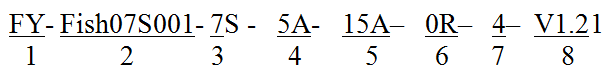
1 Feiyu company logo;
2 Protection board model - (This protection board model is Fish07S001, other types of protection boards are marked, there is no limit to the number of characters in this item)
3. The number of battery strings supported by the required protection board - (this model of protection board is suitable for 7S battery packs);
4 Charging current value - 5A means the maximum support for continuous 5A charging;
5 Discharge current value - 15A means maximum support for continuous charging of 15A;
6 Balance resistance size - fill in the value directly, for example, 100R, then the balance resistance is 100 ohms;
7 Battery type - one digit, the specific serial number indicates the battery type as follows;
|
1 |
Polymer |
|
2 |
LiMnO2 |
|
3 |
LiCoO2 |
|
4 |
LiCoxNiyMnzO2 |
|
5 |
LiFePO4 |
8 The model number of this protection board is: FY-Fish07S001-7S-5A-15A-0R-4-V1.2. When placing bulk orders, please place the order according to this model number.
1. When performing charge and discharge tests on the battery pack with the protective board installed, please do not use a battery aging cabinet to measure the voltage of each cell in the battery pack, otherwise the protective board and battery may be damaged. .
2. This protection board does not have a 0V charging function. Once the battery reaches 0V, the battery performance will be severely degraded and may even be damaged. In order not to damage the battery, the user should not charge the battery for a long time (the battery pack capacity is greater than 15AH, and the storage exceeds 1 Months) When not in use, it needs to be charged regularly to replenish the battery; when in use, it must be charged in time within 12 hours after being discharged to prevent the battery from being discharged to 0V due to self-consumption. Customers are required to have an obvious sign on the battery casing that the user regularly maintains the battery.
3. This protection board does not have reverse charging protection function. If the polarity of the charger is reversed, the protection board may be damaged.
4. This protective board shall not be used in medical products or products that may affect personal safety.
5. Our company will not be responsible for any accidents caused by the above reasons during the production, storage, transportation and use of the product.
6. This specification is a performance confirmation standard. If the performance required by this specification is met, our company will change the model or brand of some materials according to the order materials without further notification.
7. The short-circuit protection function of this management system is suitable for a variety of application scenarios, but it does not guarantee that it can be short-circuited under any conditions. When the total internal resistance of the battery pack and short-circuit loop is less than 40mΩ, the battery pack capacity exceeds the rated value by 20%, the short-circuit current exceeds 1500A, the inductance of the short-circuit loop is very large, or the total length of the short-circuited wire is very long, please test by yourself to determine whether This management system can be used.
8. When welding battery leads, there must be no wrong connection or reverse connection. If it is indeed connected incorrectly, the circuit board may be damaged and needs to be retested before it can be used.
9. During assembly, the management system should not directly contact the surface of the battery core to avoid damaging the circuit board. The assembly must be firm and reliable.
10. During use, be careful not to touch the lead tips, soldering iron, solder, etc. on the components on the circuit board, otherwise the circuit board may be damaged.
Pay attention to anti-static, moisture-proof, waterproof, etc. during use.
11. Please follow the design parameters and usage conditions during use, and the values in this specification must not be exceeded, otherwise the management system may be damaged. After assembling the battery pack and management system, if you find no voltage output or failure to charge when you power on for the first time, please check whether the wiring is correct.
Note: After your company receives the prototype and specifications, please reply promptly. If there is no reply within 7 days, our company will regard your company as having recognized the specifications and send the prototype. If your order exceeds 50 PCS, you need to sign back the acknowledgment letter. If you do not sign back, our company will also regard your company as having approved this specification and send the sample machine. The pictures in the specification are of general models and may be slightly different from the sample machine. Jiangsu Wuyun Transmission Machinery Co., Ltd. reserves the right of final interpretation of this specification.
DISCLAIM:
In order to improve the design or performance and to supply the best possible products, Feiyu reserves the right to make changes to the products contained in this data sheet. Feiyu assumes no responsibility for the use of any circuits shown in this data sheet, conveys no license under any patent or other rights, and makes no claim that the circuits are free from patent infringement. Applications for any devices shown in this data sheet are for illustration only and Feiyu makes no claim or warranty that such applications will be suitable for the use specified without further testing or modification.
LIFE RELATED POLICY:
In situations where semiconductor component failure may endanger life, system designers using this product should design the system with appropriate error detection and correction, redundancy and back-up features to prevent such an occurrence.
Feiyu’s products are not authorized for use in critical components in life support devices or systems.
1. Life support devices or systems are devices or systems which, (a) are intended for surgical implant into the body, or (b) support or sustain life, and whose failure to perform, when properly used in accordance with instructions for use provided in the labeling, can be reasonably expected to result in a significant injury to the user.
2. A critical component is any component of a life support device or system whose failure to perform can be reasonably expected to cause the failure of the life support device or system, or to affect its safety or effectiveness.