


As dedicated Smart BMS with RS485 Communication for E-bike manufacturers committed to excellence, FY•X ensures that these BMS solutions meet the highest standards of innovation and performance. Elevate your E-bike experience with FY•X's cutting-edge technology, offering reliable and efficient power management solutions. Choose FY•X for top-tier E-bike components that redefine your riding experience.
FY•X, a renowned manufacturer in China, proudly presents a state-of-the-art lineup of smart Battery Management Systems (BMS) designed specifically for E-bikes. Explore our comprehensive range, which includes the high-performance Smart BMS with RS485 Communication for E-bike. As dedicated manufacturers committed to pushing technological boundaries, FY•X ensures that these smart BMS units stand out for their innovation, providing E-bike enthusiasts with unparalleled power management solutions. Choose FY•X for cutting-edge technology and reliable BMS solutions, enhancing your E-bike experience to new heights.
This product is a protective board solution specially designed by Wenhong Technology Company for power supply 13-14 string battery packs. It is suitable for lithium batteries with different chemical properties and different numbers of strings, such as lithium ion, lithium polymer, lithium iron phosphate, etc.
BMS has two communication interfaces, RS485 and CAN (choose one of the two), which can be used to set various protection voltage, current, temperature and other parameters, and is very flexible. The maximum sustainable discharge current can reach 80A. The protection board has LED power indicator and system operation indicator light, which can conveniently display various statuses.
● 13 batteries are protected in series.
● Charging and discharging voltage, current, temperature and other protection functions.
● Output short circuit protection function.
●Two-channel battery temperature, BMS ambient temperature, FET temperature detection and protection.
● Passive balancing function.
● Accurate SOC calculation and real-time estimation.
● Protection parameters can be adjusted through the host computer.
● Can communication can monitor battery pack information through the host computer or other instruments.
● Multiple sleep modes and wake-up methods.
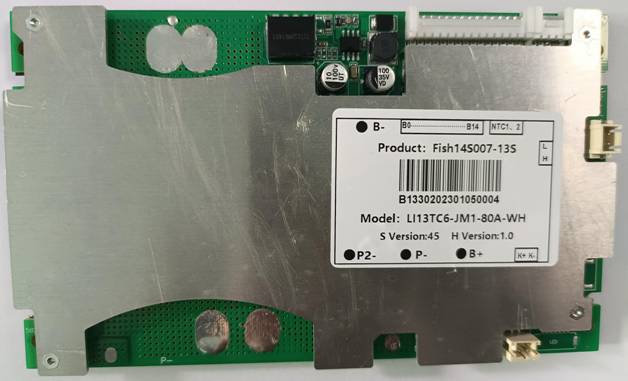
Figure 1: Real picture of the front of the BMS

Figure 2: Real picture of the back of BMS
|
Details |
Min. |
Typ. |
Max |
Error |
Unit |
|
|
Battery |
||||||
|
Battery Gas |
LiCoxNiyMnzO2 |
|
||||
|
Battery Links |
13S |
|
||||
|
Absolute Maximum Rating |
||||||
|
Input Charging Voltage |
|
54.6 |
|
±1% |
V |
|
|
Input Charging Current |
|
7 |
10 |
|
A |
|
|
Output Discharging Voltage |
36.4 |
46.8 |
54.6 |
|
V |
|
|
Output Discharging Current |
|
|
75 |
|
A |
|
|
Continuous Output Discharging Current |
≤75 |
A |
||||
|
Ambient Condition |
||||||
|
Operating Temperature |
-40 |
|
85 |
|
℃ |
|
|
Humidity (No Water-Drop) |
0% |
|
|
|
RH |
|
|
Storage |
||||||
|
Temperature |
-20 |
|
65 |
|
℃ |
|
|
Humidity (No Water-Drop) |
0% |
|
|
|
RH |
|
|
Protection Parameters |
||||||
|
Over-Charge Voltage Protection 1 (OVP1) |
4.1700 |
4.220 |
4.270 |
±50mV |
V |
|
|
Over-Charge Voltage Protection Delay Time1(OVPDT1) |
1 |
3 |
6 |
|
S |
|
|
Over-Charge Voltage Protection 2(OVP2) |
4.250 |
4.300 |
4.350 |
±50mV |
V |
|
|
Over-Charge Voltage Protection Delay Time2 (OVPDT1) |
2 |
4 |
7 |
|
S |
|
|
Over-Charge Voltage Protection Release (OVPR) |
4050 |
4.100 |
4150 |
±50mV |
V |
|
|
Over-Discharge Voltage Protection 1 (UVP1) |
2.700 |
2.800 |
2.900 |
±100mV |
V |
|
|
Over-Discharge Voltage Protection Delay Time 1(UVPDT1) |
1 |
3 |
6 |
|
S |
|
|
Over-Discharge Voltage Protection 2 (UVP2) |
2.400 |
2.500 |
2.600 |
±100mV |
V |
|
|
Over-Discharge Voltage Protection Delay Time 2(UVPDT2) |
6 |
8 |
11 |
|
S |
|
|
Over-Discharge Voltage Protection Release (UVPR) |
2.900 |
3.000 |
3.100 |
±100mV |
V |
|
|
P2- Undervoltage protection voltage |
3.000 |
3.100 |
3.200 |
±100mV |
V |
|
|
P2- Under voltage protection release voltage |
3.200 |
3.300 |
3.400 |
±100mV |
V |
|
|
Over-Current Charge Protection 1 (OCCP1) |
25 |
26 |
30 |
|
A |
|
|
Over-Current Charge Protection Delay Time1 (OCPDT1) |
3 |
5 |
8 |
|
S |
|
|
Over-Current Charge Protection Release1 |
Automatic release or discharge with a delay of 30±5s |
|||||
|
Over-Current Discharge Protection0 (OCDP0) |
67 |
75 |
83 |
|
A |
|
|
Over-Current Protection Delay Time0 (OCPDT0) |
1 |
3 |
6 |
|
S |
|
|
Over-Current Discharge Protection Release 0 |
Automatic release or discharge with a delay of 30±5s |
S |
||||
|
Over-Current Discharge Protection1 (OCDP1) |
200 |
220 |
250 |
|
A |
|
|
Over-Current Protection Delay Time1 (OCPDT1) |
40 |
80 |
250 |
|
mS |
|
|
Over-Current Discharge Protection Release 1 |
Automatic release or discharge with a delay of 30±5s |
|||||
|
Short circuit current protection |
446 |
|
1000 |
|
A |
|
|
Short circuit current protection delay time |
|
400 |
800 |
|
uS |
|
|
Short circuit protection Release |
Disconnect the load and delay 30±5s to automatically release or charge |
|||||
|
Short circuit specification
|
Short circuit description: If the short circuit current is less than the minimum value or higher than the maximum value, short circuit protection may fail. If the short circuit current is more than 1000A, short circuit protection is not guaranteed, and it is not recommended to perform a short circuit protection test. |
|||||
Note: Different chips, the corresponding power consumption is different;
Design Capacity: The design capacity of the battery pack (for this product, this value is set to 30000mAH)
Cycle Capacity: Only the discharge process is measured. Whenever the accumulated discharged power reaches this value, the number of cycles will be automatically increased by one, the register will be cleared, and the next measurement will be restarted. (This product is set to 24000mAH)
Actual capacity (Full Chg Capacity): The actual capacity of the battery pack, that is, the value saved inside the BMS after power learning, will be updated to the actual capacity value of the battery as the battery is used. The initial value setting here is the same as the design capacity. (For this product, this value is set to 30000mAH)
Full Charge Voltage: During the charging process, only when (the voltage obtained by dividing the total voltage by the number of battery strings – Taper Voltage Margin) is greater than this voltage, and the charging current is less than the charging end current for a certain period of time (i.e. Taper Timer) Only then does the chip consider the battery to be fully charged. (This product is set to 4100mV)
Charging end current (Taper Current): During the charging process, the voltage obtained by dividing the total voltage of the battery pack by the number of battery strings is greater than the full voltage.
After the voltage and the charging current gradually decrease to less than this charging end current, the chip considers that the battery is fully charged (this value is set to 1000mA for this product)
EDV2: When the battery pack is discharging, if the total voltage of the battery pack divided by the number of battery strings is less than EDV2, the chip will stop this capacity meter at this time.
number. (This product is set to 3440mV)
EDV0: When the battery pack is discharging, when the total voltage of the battery pack divided by the number of battery strings is less than EDV0, the chip determines that the battery pack has
Completely discharge the battery. (For this product, this value is set to 3200mV)
Self-discharge rate: the self-discharge capacity compensation value of the battery when it is at rest. The chip will compensate the self-discharge and maintenance of the battery pack when the battery is at rest based on this value.
The power consumption reduced by the shield itself. (This product is set to 0.2%/day)
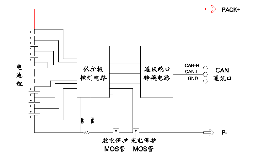
Figure 7: Protection schematic diagram

Figure 8: Dimensions 155*92 Unit: mm Tolerance: ±0.5mm
Protection plate thickness: less than 15mm (including components)
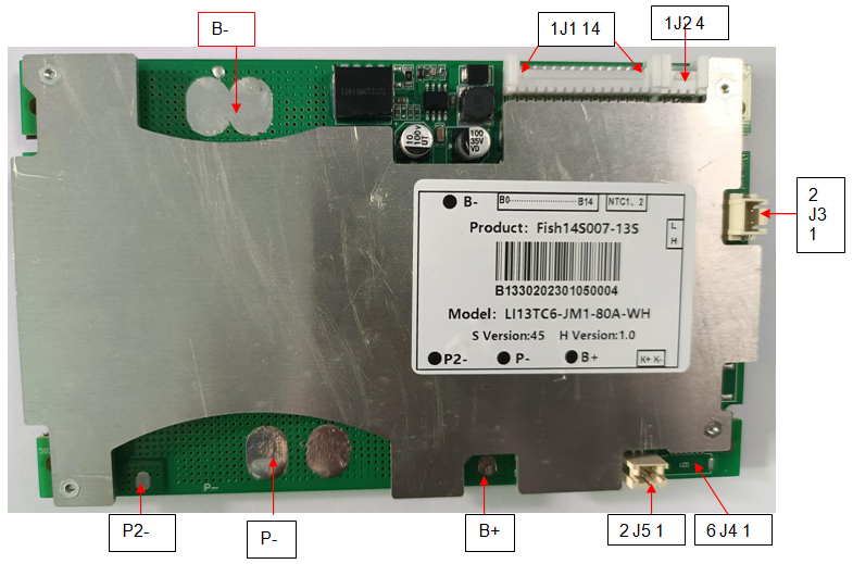
Figure 9: Wiring diagram of the protection board
|
Item |
Details |
|
|
B+ |
Connect to Positive Side of the pack. |
|
|
B- |
Connect to Negative Side of the pack. |
|
|
P- |
Charging and Discharging Negative Port. |
|
|
P2- |
Small current discharge negative port |
|
|
J1 |
1 |
Connect to Negative of Cell 1. |
|
2 |
Connect to Positive Side of Cell 1. |
|
|
3 |
Connect to Positive Side of Cell 2. |
|
|
4 |
Connect to Positive Side of Cell 3. |
|
|
5 |
Connect to Positive Side of Cell 4. |
|
|
6 |
Connect to Positive Side of Cell 5. |
|
|
7 |
Connect to Positive Side of Cell 6 |
|
|
8 |
Connect to Positive Side of Cell 7 |
|
|
9 |
Connect to Positive Side of Cell 8 |
|
|
10 |
/ |
|
|
11 |
Connect to Positive Side of Cell 9 |
|
|
12 |
Connect to Positive Side of Cell 10 |
|
|
13 |
Connect to Positive Side of Cell 11 |
|
|
14 |
Connect to Positive Side of Cell 12 |
|
|
15 |
Connect to Positive Side of Cell 13 |
|
|
J2(NTC) |
1 |
NTC1 (10K) |
|
2 |
||
|
3 |
NTC2 (10K) |
|
|
4 |
||
|
J3(Communication) |
1 |
CANH |
|
2 |
CANL |
|
|
J5(Switch base) |
1 |
Electronic switch K- |
|
2 |
Electronic switch K+(battery positive) |
|
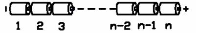
Figure 10: Battery connection sequence diagram


