


FY•X is a 10S 36V 13S 48V 15S 52V 15A Hardware BMS for E-bike manufacturer located in China. Its unique battery management system provides reliable performance and safety for e-bikes. These BMS devices are designed to support 15A current, ensuring efficient energy conversion and long-lasting battery life. As China's leading electric bicycle hardware provider, FY•X is committed to providing users with advanced technology and reliable products to promote the development of electric travel.
The 10S 36V 13S 48V 15S 52V 15A Hardware BMS for E-bike BMS (battery management system) provided by FY•X Chinese manufacturer is an efficient solution. These BMS devices support 15A current management to ensure the safe and stable operation of the battery pack. FY•X is known for its superior manufacturing technology and reliability, providing reliable battery protection for electric bicycles. These BMS use advanced technology to ensure intelligent monitoring and management of batteries, improving the performance and lifespan of the entire system. Choosing FY•X’s BMS is an investment in reliability and performance, providing riders with a safer and more reliable e-bike experience.
This product is a protective board solution specially designed by Wenhong Technology Company for 13-string battery packs such as electric bicycles and motorcycles. It can be applied to lithium batteries with different chemical properties, such as lithium ion, lithium polymer, etc. The protection board has strong load capacity and the maximum continuous current can be 20A.
● 13 battery cells are protected in series;
● Charging and discharging voltage, temperature, overcurrent and other protection functions;
● Low power consumption.

Figure 1: Real picture of the front of the BMS
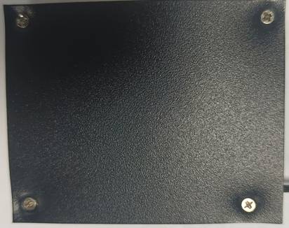
Figure 2: Real picture of the back of BMS
|
Details |
Min. |
Typ. |
Max |
Error |
Unit |
|||||
|
Battery |
||||||||||
|
Battery Gas |
LiCoxNiyMnzO2 |
|
||||||||
|
Battery Links |
13S |
|
||||||||
|
Absolute Maximum Rating |
||||||||||
|
Input Charging Voltage |
|
54.6 |
|
±1% |
V |
|||||
|
Input Charging Current |
|
10 |
15 |
|
A |
|||||
|
Output Discharging Voltage |
27 |
48 |
54 |
|
V |
|||||
|
Output Discharging Current |
|
|
20 |
|
A |
|||||
|
Continuous Output Discharging Current |
≤20 |
A |
||||||||
|
Ambient Condition |
||||||||||
|
Operating Temperature |
-20 |
|
75 |
|
℃ |
|||||
|
Humidity (No Water-Drop) |
0% |
|
|
|
RH |
|||||
|
Storage |
||||||||||
|
Temperature |
-40 |
|
85 |
|
℃ |
|||||
|
Humidity (No Water-Drop) |
0% |
|
|
|
RH |
|||||
|
Protection Parameters |
||||||||||
|
Over-Charge Voltage Protection |
4.150 |
4.200 |
4.250 |
±50mV |
V |
|||||
|
Over-Charge Voltage Protection Delay Time |
200 |
1000 |
2000 |
|
ms |
|||||
|
Over-Charge Voltage Protection Release |
4.050 |
4.100 |
4.150 |
±50mV |
V |
|||||
|
Over-Discharge Voltage Protection |
2.70 |
2.800 |
2.90 |
±100mV |
V |
|||||
|
Over-Discharge Voltage Protection Delay Time |
200 |
1000 |
2000 |
|
ms |
|||||
|
Over-Discharge Voltage Protection Release |
2.800 |
2.900 |
3.000 |
±100mV |
V |
|||||
|
Overcurrent charge protection1 (OCCP1) |
13 |
15.5 |
18 |
±2.5 |
A |
|||||
|
Overcurrent charge protection1 delay time |
1 |
3 |
5 |
±2 |
S |
|||||
|
Overcurrent charge protection1 release |
Remove charger delay 5 seconds |
|||||||||
|
Discharge overcurrent 1 protection |
47 |
52.5 |
58 |
±5.5 |
A |
|||||
|
Discharge overcurrent 1 protection delay |
500 |
1000 |
2000 |
|
ms |
|||||
|
Discharge overcurrent 1 Protection release |
The device recovers after a delay of 30 seconds, but locks after four consecutive overflows within one minute, and recovers or charges after removing the load for 10 seconds |
|
||||||||
|
Discharge overcurrent 2 protection |
70 |
80 |
90 |
±10 |
A |
|||||
|
Discharge overcurrent 2 protection delay |
30 |
50 |
70 |
±20 |
ms |
|||||
|
Discharge overcurrent 2 protection release |
The device recovers after a delay of 30 seconds, but locks after four consecutive overflows within one minute, and recovers or charges after removing the load for 10 seconds |
|
||||||||
|
Short circuit protection |
160 |
|
600 |
|
A |
|||||
|
Short circuit protection delay |
320 |
|
500 |
|
us |
|||||
|
Short circuit protection release |
Remove the load and restore or charge after 10 seconds |
|
||||||||
|
Short circuit specification |
Short circuit: If the short circuit current is less than the minimum or higher than the maximum, the short circuit protection may fail. If the short circuit current is more than 600A, the short circuit protection is not guaranteed, and it is not recommended to perform a short circuit protection test |
|||||||||
|
Discharge high temperature protection |
65 |
70 |
75 |
±5 |
℃ |
|||||
|
Discharge high temperature protection release |
55 |
60 |
65 |
±5 |
℃ |
|||||
|
Low temperature discharge protection |
-30 |
-25 |
-20 |
±5 |
℃ |
|||||
|
Discharge low temperature protection release |
-25 |
-20 |
-15 |
±5 |
℃ |
|||||
|
Charging high temperature protection |
60 |
65 |
70 |
±5 |
℃ |
|||||
|
Charge high temperature protection release |
50 |
55 |
60 |
±5 |
℃ |
|||||
|
Charge low temperature protection |
-10 |
-5 |
0 |
±5 |
℃ |
|||||
|
Charge low temperature protection release |
-5 |
0 |
5 |
±5 |
℃ |
|||||
|
Current Consumption |
||||||||||
|
Sleep Consumption |
|
50 |
100 |
|
uA |
|||||
|
Over-Discharge Consumption |
|
35 |
80 |
|
uA |
|||||
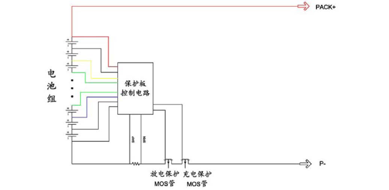
Figure 7: Protection schematic diagram
PCB and size structure drawing
Figure 8: Top board wiring diagram
Figure 9: Mainboard bottom wiring diagram

Figure 10: Dimensions 65*52 Unit: mm Tolerance: ±0.5mm
Protection plate thickness: less than 12mm (including components)
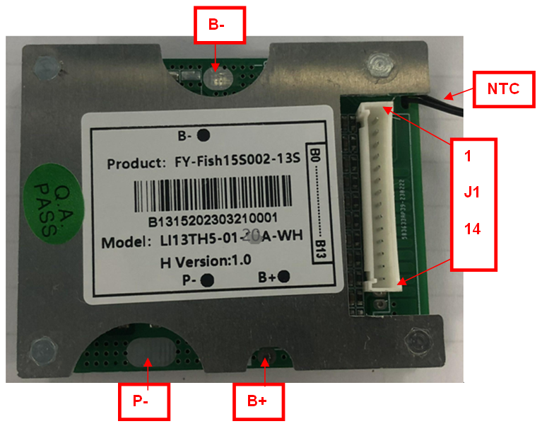
Figure 11: Wiring diagram of the protection board
|
Item |
Details |
||
|
B+ |
Connect to Positive Side of the pack. |
||
|
B- |
Connect to Negative Side of the pack. |
||
|
P- |
Charging and Discharging Negative Port. |
||
|
J1 |
1 |
BC0 |
Connect to Negative Side of Cell 1. |
|
2 |
BC1 |
Connect to Positive Side of Cell 1. |
|
|
3 |
BC2 |
Connect to Positive Side of Cell 2. |
|
|
4 |
BC3 |
Connect to Positive Side of Cell 3. |
|
|
5 |
BC4 |
Connect to Positive Side of Cell 4. |
|
|
6 |
BC5 |
Connect to Positive Side of Cell 5. |
|
|
7 |
BC6 |
Connect to Positive Side of Cell 6. |
|
|
8 |
BC7 |
Connect to Positive Side of Cell 7. |
|
|
9 |
BC8 |
Connect to Positive Side of Cell 8. |
|
|
10 |
BC9 |
Connect to Positive Side of Cell 9. |
|
|
11 |
BC10 |
Connect to Positive Side of Cell 10. |
|
|
|
12 |
BC11 |
Connect to Positive Side of Cell 11. |
|
|
13 |
BC12 |
Connect to Positive Side of Cell 12. |
|
|
14 |
BC13 |
Connect to Positive Side of Cell 13. |
|
NTC |
Temperature probe |
||
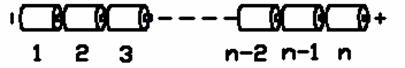
Figure 12: Battery connection sequence diagram
Preparation: According to the definition shown in Figure 11, connect the corresponding voltage detection cable to the corresponding battery core. Please pay attention to the order in which the sockets are marked.
Steps to install protective board:
Step 1: Weld the P- and wires to the corresponding positions of the protection board without connecting the charger and load.
Step 2: Connect the negative pole of the battery pack to B- of the protection board;
Step 3: Connect the positive terminal of the battery pack to B+ of the protection board;
Step 4: Connect the battery pack and battery rows to J1 of the protection board;
Steps to remove the protective plate:
Step 1: Disconnect all chargers\loads
Step 2: Unplug the battery pack’s battery strip connector J1;
Step 3: Remove the connecting wire connecting the positive electrode of the battery pack from the B+ pad of the protective plate
Step 4: Remove the connecting wire connecting the negative electrode of the battery pack from the B- pad of the protective plate
Additional notes: Please pay attention to electrostatic protection during production operations.


