


Discover the FY•X 10S 36V 13S 48V 25A BMS for E-bike, a high-end hardware solution for E-bikes. Proudly supplied from China, this BMS ensures superior safety standards, with a robust 25A capacity. Trust FY•X for a secure and reliable E-bike experience.
Introducing the FY•X 10S 36V 13S 48V 25A BMS for E-bike. Engineered with precision by reputable suppliers in China, this Battery Management System (BMS) ensures the utmost safety for electric bikes. With a robust 25A capacity for both charging and discharging, it meets the highest standards, including UL2271 certification. The FY•X BMS is the epitome of high-end hardware, providing reliability and security to elevate your E-bike experience.
This product is a BMS (Battery Management System) designed specifically for certified electric unicycle battery packs by Feiyu New Energy. It is compatible with 13-series lithium batteries of different chemical compositions, such as lithium-ion, lithium polymer, lithium iron phosphate, etc. The BMS features dual charging and discharging protection for enhanced safety. The protection board has a strong load-bearing capacity, supporting a maximum sustainable discharge current of up to 25A.
- Protection for a 13-cell battery pack in series.
- Protection functions for charging and discharging voltage, current, temperature, etc.
- Output short circuit protection.
- High and low-temperature protection during charging and discharging.
- Secondary protection for charging and discharging.
- Anti-reverse charging function for the charging port.
- Charging and discharging cut-off function.
Front view of BMS (the picture does not match the actual object and is for reference only)

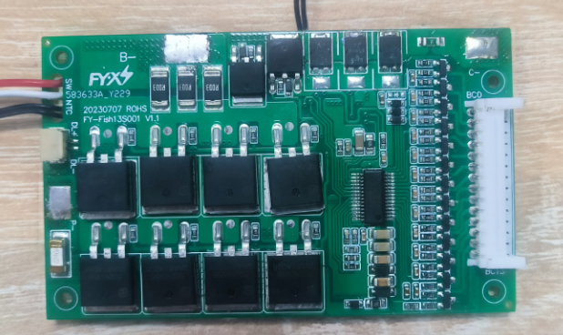
Actual picture of the reverse side of BMS (the picture does not match the actual object and is for reference only)

Dimension 87*52.5 Unit: mm Tolerance: ±0.5mm
Protection board thickness: less than 15mm (including components)
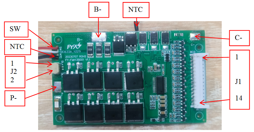
Protection board wiring diagram
|
Item |
Details |
|
|
B- |
Connect to Negative Side of the pack. |
|
|
P- |
Discharging Negative Port. |
|
|
C- |
Charging Negative Port. |
|
|
J1 |
1 |
B0 Connect to Negative Side of Cell1 |
|
2 |
B1 Connect to Positive Side of Cell 1 |
|
|
3 |
B2 Connect to Positive Side of Cell 2 |
|
|
4 |
B3 Connect to Positive Side of Cell 3 |
|
|
5 |
B4 Connect to Positive Side of Cell 4 |
|
|
6 |
B5 Connect to Positive Side of Cell 5 |
|
|
7 |
B6 Connect to Positive Side of Cell 6 |
|
|
8 |
B7 Connect to Positive Side of Cell 7 |
|
|
9 |
B8 Connect to Positive Side of Cell 8 |
|
|
10 |
B9 Connect to Positive Side of Cell 9 |
|
|
11 |
B10 Connect to Positive Side of Cell 10 |
|
|
12 |
B11 Connect to Positive Side of Cell 11 |
|
|
13 |
B12 Connect to Positive Side of Cell 12 |
|
|
14 |
B13 Connect to Positive Side of Cell 13 |
|
|
J2 |
1 |
DL+ Power display output positive |
|
2 |
DL- Power display output negative |
|
|
SW |
|
Weak current switch controls the discharge MOS. Close the switch to open the discharge output, and open the switch to close the discharge output. |
|
NTC |
|
Temperature Sensor |
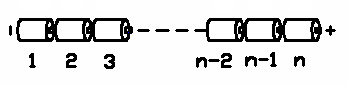
Schematic diagram of battery connection sequence
Warning: When connecting the protective plate to the battery cells or removing the protective plate from the battery pack, the following connection sequence and regulations must be followed; if operations are not performed in the required order, the components of the protective plate will be damaged, resulting in the protective plate being unable to protect the battery. core, causing serious consequences.
Preparation: As shown in Figure 11, connect the corresponding voltage detection cable to the corresponding battery core. Please pay attention to the order in which the sockets are marked.
Steps to install protective board:
Step 1: Solder the P-/C- wires to the P-/C- pads of the protection board without connecting the charger and load;
Step 2: Weld the SW weak current switch wire to the weak current switch of the battery pack;
Step 3: Connect the power board input line to the J2 socket;
Step 4: Connect the negative electrode of the battery pack to B- of the protection board;
Step 5: Connect the detection cable to the J1 socket of the protection board;
Steps to remove the protective plate:
Step 1: Disconnect all chargers\loads
Step 2: Unplug the voltage detection cable of the protection board
Step 3: Remove the power board connection wire, disconnect the weak current switch wire, and remove the P-/C- wire from the P-/C- pad
Step 4: Remove the connecting wire connecting the negative electrode of the battery pack from the B- pad of the protective plate
Additional notes: Please pay attention to electrostatic protection during production operations.


