


FY•X, a trusted name among Suppliers, introduces a range of smart Battery Management Systems (BMS) designed for E-bikes. Our selection includes the Smart BMS 13S 48V UART Communication, each featuring a robust 16A capacity and advanced UART Communication capabilities. As Suppliers committed to excellence, FY•X ensures these smart BMS units are at the forefront of innovation, delivering efficient power management solutions for E-bike enthusiasts. Elevate your E-bike experience with FY•X's cutting-edge technology and reliable BMS solutions.
FY•X, a leading supplier in the industry, presents a range of smart Battery Management Systems (BMS) specifically designed for E-bikes. Our selection includes the Smart BMS 13S 48V UART Communication, each featuring a 16A capacity and advanced UART Communication capabilities. As committed suppliers, FY•X prioritizes excellence, delivering innovative BMS solutions that ensure safe and efficient power management for E-bike enthusiasts. Choose FY•X for cutting-edge technology and reliable performance in the world of smart BMS for electric bikes.
This product is a protective board solution specially designed by Wenhong Technology Company for 14-string battery packs for shared electric bicycles. It is suitable for lithium batteries with different chemical properties and different numbers of strings, such as lithium ion, lithium polymer, lithium iron phosphate, etc.
BMS has a UART communication interface that can be used to set various protection voltage, current, temperature and other parameters, which is very flexible.
The protection board has strong load capacity, and the maximum sustainable discharge current can reach 16A. The protection board has LED power indicator (reserved) and system operation indicator light, which can conveniently display various statuses.
● 14 batteries are protected in series.
●Charging and discharging voltage, current, temperature and other protection functions.
● Output short circuit protection function.
● 1-channel battery temperature detection and protection.
● Accurate SOC calculation and real-time estimation.
● Protection parameters can be adjusted through the host computer.
● Communication can monitor battery pack information through the host computer or other instruments.
● Low power consumption
Figure 1: BMS front view
Figure 2: Physical picture of the back of BMS
|
Details |
Min. |
Typ. |
Max |
Error |
Unit |
|
|
Battery |
||||||
|
BatteryGas |
LiCoxNiyMnzO2 |
|
||||
|
BatteryLinks |
10S |
|
||||
|
AbsoluteMaximumRating |
||||||
|
InputChargingVoltage |
|
42 |
|
±1% |
V |
|
|
InputChargingCurrent |
|
2 |
5 |
|
A |
|
|
OutputDischargingVoltage |
42 |
50.4 |
44.8 |
|
V |
|
|
OutputDischargingCurrent |
|
|
16 |
|
A |
|
|
ContinuousOutputDischargingCurrent |
≤16 |
A |
||||
|
AmbientCondition |
||||||
|
OperatingTemperature |
-40 |
|
85 |
|
℃ |
|
|
Humidity(NoWater-Drop) |
0% |
|
|
|
RH |
|
|
Storage |
||||||
|
Temperature |
-20 |
|
65 |
|
℃ |
|
|
Humidity(NoWater-Drop) |
0% |
|
|
|
RH |
|
|
ProtectionParameters |
||||||
|
Over-ChargeVoltageProtection1(OVP1) |
|
4.200 |
|
±30mV |
V |
|
|
Over-ChargeVoltageProtectionDelayTime1(OVPDT1) |
|
3 |
|
±2 |
S |
|
|
Over-ChargeVoltageProtection2(OVP2) |
|
4.300 |
|
±30mV |
V |
|
|
Over-ChargeVoltageProtectionDelayTime2(OVPDT1) |
|
4 |
|
±2 |
S |
|
|
Over-ChargeVoltageProtectionRelease(OVPR) |
|
4.100 |
|
±50mV |
V |
|
|
Over-DischargeVoltageProtection1(UVP1) |
|
3.000 |
|
±80mV |
V |
|
|
Over-DischargeVoltageProtectionDelayTime1(UVPDT1) |
|
5 |
|
±2 |
S |
|
|
Over-DischargeVoltageProtection2(UVP2) |
|
2.500 |
|
±80mV |
V |
|
|
Over-DischargeVoltageProtectionDelayTime2(UVPDT2) |
|
8 |
|
±2 |
S |
|
|
Over-DischargeVoltageProtectionRelease(UVPR) |
|
3.200 |
|
±100mV |
V |
|
|
Over-CurrentChargeProtection1(OCCP1) |
|
8 |
|
±1 |
A |
|
|
Over-CurrentChargeProtectionDelayTime1(OCPDT1) |
|
3 |
|
|
S |
|
|
Over-CurrentChargeProtectionRelease1 |
Automatic release after 30 seconds |
|||||
|
Over-CurrentDischargeProtection0(OCDP0) |
|
22 |
|
±5 |
A |
|
|
Over-CurrentProtectionDelayTime0(OCPDT0) |
|
3 |
|
|
S |
|
|
Over-CurrentDischargeProtectionRelease0 |
Automatic release after 30 seconds |
S |
||||
|
Over-CurrentDischargeProtection1(OCDP1) |
|
66 |
|
±10 |
A |
|
|
Over-CurrentProtectionDelayTime1(OCPDT1) |
|
80 |
|
±20 |
mS |
|
|
Over-CurrentDischargeProtectionRelease1 |
Automatic release after 30 seconds |
|||||
|
Shortcircuitcurrentprotection |
|
310 |
|
|
A |
|
|
Shortcircuitcurrentprotectiondelaytime |
|
200 |
|
|
uS |
|
|
ShortcircuitprotectionRelease |
Disconnected load and delayed 30S release |
|||||
|
ChargingTemperature |
0 |
|
65 |
±5 |
℃ |
|
|
ChargingTemperatureProtectionRelease |
5 |
|
55 |
±5 |
℃ |
|
|
DischargingTemperature |
-30 |
|
70 |
±5 |
℃ |
|
|
DischargingTemperatureProtectionRelease |
-20 |
|
60 |
±5 |
℃ |
|
|
Cellbalance |
||||||
|
BleedStartPoint |
|
- |
|
|
mV |
|
|
BleedAccuracy |
|
- |
|
|
mV |
|
|
BleedCurrent |
|
- |
|
|
mA |
|
|
BalanceMode |
- |
|||||
|
CurrentConsumption |
||||||
|
NormalMode |
|
|
10 |
|
mA |
|
|
Sleepmode |
|
100 |
200 |
|
uA |
|
|
shutdownmode |
|
30 |
60 |
|
uA |
|

Figure 7: Protection schematic diagram
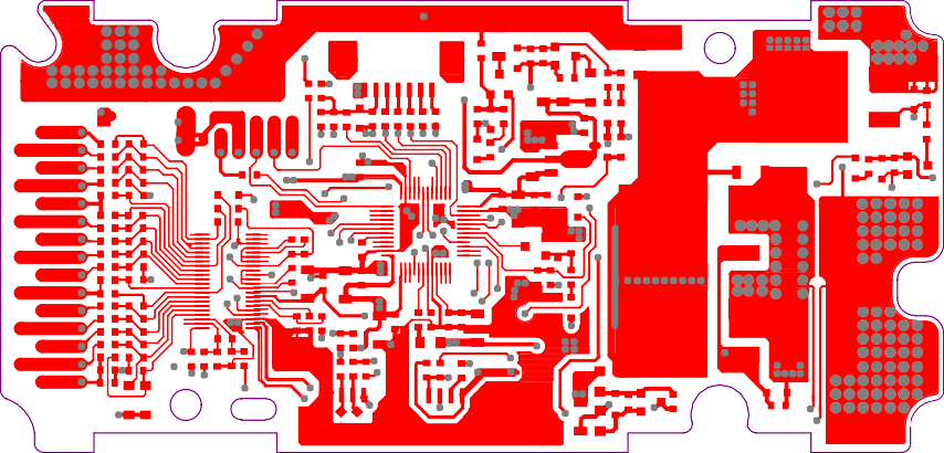
Figure 8: Top board wiring diagram
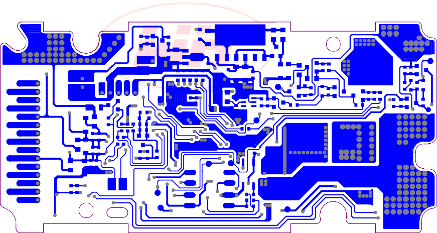
Figure 9: Mainboard bottom wiring diagram
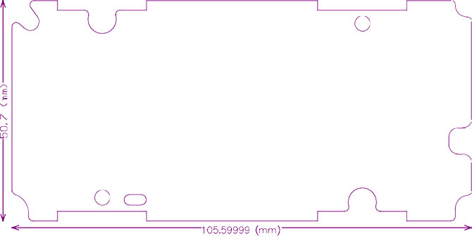
Figure 10: Dimensions 105.6*50.7 Unit: mm
Tolerance: ±0.5mm Thickness: less than 15mm (including components)
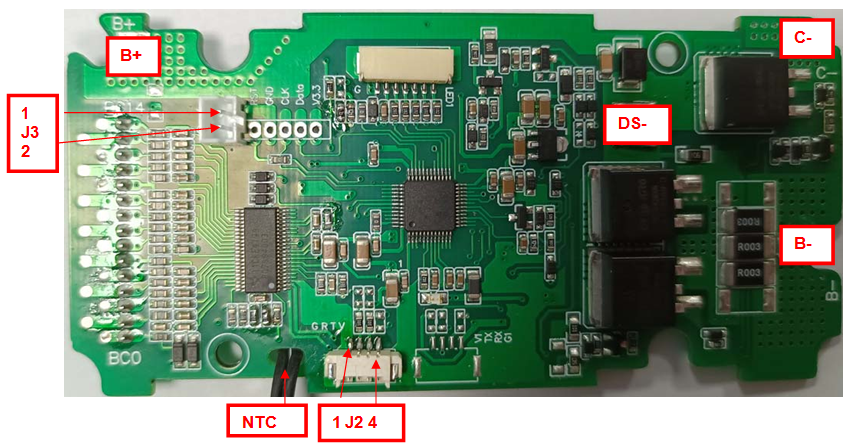

Figure 11: Wiring diagram of the protection board
Charging J3 port is high level, discharging and static, J3 port is low level, high level is provided by external controller pull-up.
|
Item |
Details |
|
|
B+ |
ConnecttoPositiveSideofthepack. |
|
|
B- |
ConnecttoNegativeSideofthepack. |
|
|
DS- |
DischargingNegativePort. |
|
|
C- |
ChargingNegativePort. |
|
|
J1 |
B0 |
ConnecttoNegativeofCell1. |
|
B1 |
ConnecttoPositiveSideofCell1. |
|
|
B2 |
ConnecttoPositiveSideofCell2. |
|
|
B3 |
ConnecttoPositiveSideofCell3. |
|
|
B4 |
ConnecttoPositiveSideofCell4. |
|
|
B5 |
ConnecttoPositiveSideofCell5. |
|
|
B6 |
ConnecttoPositiveSideofCell6 |
|
|
B7 |
ConnecttoPositiveSideofCell7 |
|
|
B8 |
ConnecttoPositiveSideofCell8 |
|
|
B9 |
ConnecttoPositiveSideofCell9 |
|
|
B10 |
ConnecttoPositiveSideofCell10 |
|
|
B11 |
ConnecttoPositiveSideofCell11 |
|
|
B12 |
ConnecttoPositiveSideofCell12 |
|
|
B13 |
ConnecttoPositiveSideofCell13 |
|
|
B14 |
ConnecttoPositiveSideofCell14 |
|
|
The J2(Internal communication) system can only be 3.3V
|
1 |
Communication ground |
|
2 |
Communication RX |
|
|
3 |
Communication TX |
|
|
4 |
/ | |
|
J3 |
1 |
Charge high level (external pull up 5V) |
|
2 |
Ground wire |
|

Figure 12: Battery connection sequence diagram
Warning: When connecting the protective plate to the battery cells or removing the protective plate from the battery pack, the following connection sequence and regulations must be followed; if operations are not performed in the required order, the components of the protective plate will be damaged, resulting in the protective plate being unable to protect the battery. core, causing serious consequences.
Preparation: As shown in Figure 11, connect the corresponding voltage detection cable to the corresponding battery core. Please pay attention to the order in which the sockets are marked.
Steps to install protective board:
Steps to install protective board:
Step 1: Weld the DS- and C- lines to the corresponding positions of the protection board without connecting the charger and load.
Step 2: Connect the negative pole of the battery pack to B- of the protection board;
Step 3: Connect the negative pole of the battery pack to B+ on the protection board;
Step 4: Insert J1
Step 5: Charge and activate.
Steps to remove the protective plate:
Step 1: Disconnect all chargers\loads
Step 2: Remove J1
Step 3: Remove the connecting wire connecting the positive electrode of the battery pack from the B+ pad of the protective plate
Step 4: Remove the connecting wire connecting the negative electrode of the battery pack from the B- pad of the protective plate
Additional notes: Please pay attention to electrostatic protection during production operations.

1 Wenhong company logo;
2 Protection board model - (This protection board model is Fish14S005, other types of protection boards are marked, there is no limit to the number of characters in this item)
3. The number of battery strings supported by the required protection board - (this model of protection board is suitable for 17S battery packs);
4 Charging current value - 8A means the maximum support for continuous 8A charging;
5 Discharge current value - 20A means the maximum support for continuous charging is 20A;
6 Balance resistance size - fill in the value directly, for example, 100R, then the balance resistance is 100 ohms;
7 Battery type - one digit, the specific serial number indicates the battery type as follows;
|
1 |
Polymer |
|
2 |
LiMnO2 |
|
3 |
LiCoO2 |
|
4 |
LiCoxNiyMnzO2池 |
|
5 |
LiFePO4 |
8 Communication method - one letter represents a communication method, I represents IIC communication, U represents UART communication, R represents RS485 communication, C represents CAN communication, H represents HDQ communication, S represents RS232 communication, 0 represents no communication, this product UC stands for UART+CAN dual communication;
9 Hardware version - V1.0 means the hardware version is version 1.0.
10 The model number of this protection board is: WH-Fish14S005-14S-5A-16A-0-4-U-V1.0. Please place the order according to this model number when placing bulk orders.


