


As the professional manufacture, we would like to provide you 13S 48V 25A BMS with UART Communication for E-bike.FY•X provides cutting-edge 13S 48V 25A Charge and Discharge Ultra Safe UL2271 Smart BMS with UART Communication specifically designed for E-bikes. As reliable suppliers, we ensure top-notch quality and safety in our BMS solutions. With advanced features and UART communication capabilities, our Smart BMS offers unparalleled performance, making it the ideal choice for high-end electric bike applications. Trust FY•X for innovative and secure energy management solutions.
FY•X offers a cutting-edge 13S 48V 25A BMS with UART Communication for E-bike Communication for E-bikes. As trusted suppliers, we provide high-end Battery Management Systems (BMS) designed to ensure utmost safety and performance. Our BMS, tailored for 13S lithium-ion batteries, boasts advanced features, including UART communication, enabling seamless integration with E-bike systems. Choose FY•X for reliable, innovative solutions that elevate the efficiency and safety of your electric bike power management.
This product is a BMS specially designed by Feiyu New Energy Technology Company for electric bicycle battery packs in the rental market. It is suitable for 13-cell lithium batteries with different chemical properties, such as lithium ion, lithium polymer, lithium iron phosphate, etc.
It has a UART communication interface, which can be used to set various protection voltage, current, temperature and other parameters, which is very flexible. Supports lossless firmware upgrade function for BMS through UART communication. The protection board has strong load capacity and the maximum sustainable discharge current can reach 25A.
● 13 batteries are protected in series.
● Charging and discharging voltage, current, temperature and other protection functions.
● Output short circuit protection function.
● 4-way temperature detection.
● External passive balancing function.
● Accurate SOC calculation and real-time estimation.
● Various fault data storage.
● Protection parameters can be adjusted through the host computer.
● UART communication can monitor battery pack information through the host computer or other instruments.
● Multiple sleep modes and wake-up methods.
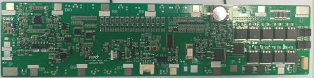
BMS front physical picture
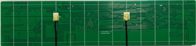
Physical picture of the reverse side of BMS
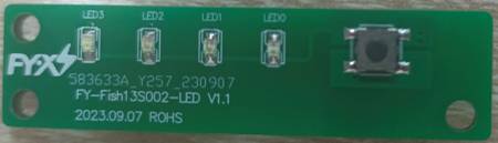
LED light board front physical picture

Real picture on the back of LED light board
Design Capacity: The design capacity of the battery pack (for this product, this value is set to 12800mAH)
Cycle Capacity: Only the discharge process is measured. Whenever the accumulated discharged electricity reaches this value, the number of cycles will be automatically increased by one, the register will be cleared, and the next measurement will be restarted. (This product is set to 10240mAH)
Full Chg Capacity: The actual capacity of the battery pack, that is, the value saved inside the BMS after power learning, will be updated to the actual capacity value of the battery as the battery is used. The initial value setting here is the same as the design capacity. (This product is set to 12800mAH)
Full Charge Voltage: During the charging process, only when (the voltage obtained by dividing the total voltage by the number of battery strings – Taper Voltage Margin) is greater than this voltage, and the charging current is less than the charging end current for a certain period of time (i.e. Taper Timer), the chip The battery is considered to be fully charged. (This product is set to 4120mV)
Taper Current: During the charging process, the voltage obtained by dividing the total voltage of the battery pack by the number of battery strings is greater than the full voltage.
After the voltage and the charging current gradually decrease to less than this charging end current, the chip considers that the battery is fully charged (this value is set to 800mA for this product)
EDV2: When the battery pack is discharging, if the total voltage of the battery pack divided by the number of battery strings is less than EDV2, the chip will stop this capacity meter at this time.
number. (This product is set to 3077mV)
EDV0: When the battery pack is discharging, when the total voltage of the battery pack divided by the number of battery strings is less than EDV0, the chip determines that the battery pack has
Completely discharge the battery. (This value is set to 2885mV for this product)
Self-discharge rate: the self-discharge capacity compensation value of the battery when it is at rest. The chip will compensate the self-discharge and maintenance of the battery pack when the battery is at rest based on this value.
The power consumption reduced by the shield itself. (This product is set to 0.2%/day)


Figure 7: Protection principle block diagram
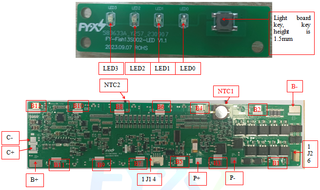
Figure 11: Protection board wiring diagram
|
Item |
Details |
|
|
B+ |
Connect to Positive Side of the pack. |
|
|
P+ |
Discharging Positive Port. |
|
|
B- |
Connect to Negative Side of the pack. |
|
|
P- |
Discharging Negative Port. |
|
|
C- |
Charging Negative Port. |
|
|
J1 |
1 |
TX communication sends signals |
|
2 |
RX communications receive signal |
|
|
3 |
NC |
|
|
4 |
K- electronic switch, short P+ effective |
|
|
|
1 |
Connect to Negative of Cell 1. |
|
2 |
Connect to Positive Side of Cell 1. |
|
|
3 |
Connect to Positive Side of Cell 2. |
|
|
4 |
Connect to Positive Side of Cell 3. |
|
|
5 |
Connect to Positive Side of Cell 4. |
|
|
6 |
Connect to Positive Side of Cell 5. |
|
|
7 |
Connect to Positive Side of Cell 6 |
|
|
8 |
Connect to Positive Side of Cell 7 |
|
|
9 |
Connect to Positive Side of Cell 8 |
|
|
10 |
Connect to Positive Side of Cell 9 |
|
|
11 |
Connect to Positive Side of Cell 10 |
|
|
12 |
Connect to Positive Side of Cell 11 |
|
|
13 |
Connect to Positive Side of Cell 12 |
|
|
14 |
Connect to Positive Side of Cell 13 |
|
|
J2(LED) |
1 |
GND |
|
2 |
STA light board switch |
|
|
3 |
LED3 Highest power indicator |
|
|
4 |
LED2 |
|
|
5 |
LED1 |
|
|
6 |
LED0 Indicates the minimum power indicator |
|
|
NTC1 |
|
10K B=3435 NTC1 |
|
NTC2 |
|
10K B=3435 NTC1 |
|
SW |
|
Panel key |
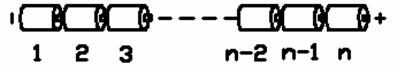
Figure 12: Schematic diagram of battery connection sequence
|
KEY |
Battery Status |
Capacity Indicator |
|||
|
LED3 |
LED2 |
LED1 |
LED0 |
||
|
NO |
-- |
OFF |
OFF |
OFF |
OFF |
|
YES |
0≤C<10% |
OFF |
OFF |
OFF |
闪 |
|
YES |
10≤C≤25% |
OFF |
OFF |
OFF |
ON |
|
YES |
25<C≤50% |
OFF |
ON |
ON |
|
|
YES |
50<C≤75% |
OFF |
ON |
ON |
ON |
|
YES |
C>75% |
ON |
ON |
ON |
ON |
Note: When the button is turned on, the LED will turn off automatically after 5 seconds. When charging, it will flash at the highest current capacity.
Warning: When connecting the protective plate to the battery cells or removing the protective plate from the battery pack, the following connection sequence and regulations must be followed; if operations are not performed in the required order, the components of the protective plate will be damaged, resulting in the protective plate being unable to protect the battery. core, causing serious consequences.


